ANITA Developed Further
The ANITA Mk 8 was very successful and had the electronic desktop calculator market to itself for over two years, from the start of 1962 to early 1964, without any serious competition.
The early computers of the 1940s and 1950s used the mature vacuum tube (thermionic valve) technology of the day. In the 1950s and early 1960s transistors were new, undergoing rapid development, and were expensive. So it is no surprise that the first commercially successful electronic desktop calculators, used vacuum tube technology.
An article of 1965 on cold cathode tubes from Mullard Ltd. (a British manufacturer of these devices, which also produced a prototype calculator using them) gives an insight into why they were used in these calculators at the time:[1]
"... They are an accountant's dream; a typical modern [cold cathode] tube has a life expectancy several thousand times better than the
conventional thermionic tube, although they employ voltages of the same order. They are much cheaper than either semiconductor devices or vacuum tubes; they do not require costly materials with a high degree of purity in
their manufacture, nor do need transformers or cooling systems to operate. The tubes require no warm-up period and they can take severe overload."
However, developments in semiconductors were very rapid. John Lloyd (Chief Engineer at Sumlock Anita Electronics) explains:
"During the 1960s silicon transistors and diodes became
available at prices we could afford to use in calculators. A design was produced which used rings of transistors in the logic instead of trigger tubes and silicon diodes. It could be a quarter the size of the Mk 8, too
small to have a full keyboard, so the logic of the Mk 12 was used, and the Anita 1000 series was launched."
The first competition for the ANITA
From early 1964 competition arrived as other companies began marketing all-transistor desktop calculators, as illustrated below. These employ Germanium transistors, rather than the now standard Silicon transistors.

From Japan came the Sharp Compet CS-10A calculator. This example was on display until recently in The Science Museum, London.
Like the early ANITA models this features a "full keyboard", which would quickly become obsolescent.

From the U.S.A. came the Friden models 130 and 132. They use a Cathode Ray Tube (a small television tube) to display four lines of calculation, and use an acoustic delay-line
memory.
These models feature a 10-key keyboard, as we now accept as standard, and the 132, shown here, also has a square root key.

From Italy came the IME 84, made by Industria Macchine Elettroniche, "a company of the Edison group".
This also has a 10-key keyboard, and utilises a magnetic-core memory.
For more details of these competitors visit the Vintage Calculator Web Museum.
Responding to the competition
Initially the competing electronic calculators were no cheaper nor smaller than the ANITA, but Bell Punch responded by opening a new research and development building on its Uxbridge site, and electronics research was increased for the calculators and the other Bell Punch products.
An article in the now defunct local newspaper the Hillingdon Mirror in May 1967 featured the new facility. Here are a few extracts:


The Lamson Industries (the parent company) annual report for 1967[2] mentions the ANITA Mk 12 "Several of the research achievements of 1966 are illustrated in the report. Foremost was the introduction of Anita Mark 12, a simplified keyboard electronic calculator designed in the first instance for the continental market, and now coming into production."

The ANITA Mk 12, the first ANITA calculator with the, fast becoming standard, 10-key keyboard, rather than the previous 'full' keyboards.
John Sparkes relates details of the development of the ANITA range:
"The demand for more and more features to be included in
ANITA resulted in the introduction of the Mk9 with a chain multiplication feature and the Mk10 with the capability of displaying results in sterling [£sd] currency. These machines required some additional mechanism design and a considerable increase in the amount of 'hard' wiring which introduced production and service difficulties. Further development of the ANITA as a full keyboard machine was exhausted.
The introduction of the ANITA Mk11 & Mk12 with a '10-key' keyboard was a major step forward although the overall size of the machines remained the same as their predecessors. As a matter of expediency I retained the original base and rear mouldings and redesigned the top moulding and keyplate. To circumvent the lead time necessary to produce injection moulded top mouldings we found a local company who were able to manufacture a quantity in fibreglass. Only five keylines were necessary to carry the 0-9 and control keys, and whereas the keylines in the first ANITA'S ran north to south, those in the Mk11 & Mk12 ran east to west and the interior chassis arrangement was correspondingly different. With the reduction of the number of keylines from 13 to 5, and the increasing availability of transistors and diodes, there was more space for the electronics. This in turn allowed the partitioning of the printed circuits to be improved and the amount of 'hard' wiring to be reduced — very desirable from a production and service point of view.
For the Annual General Meeting of Lamson Industries Ltd. in April 1968 it was reported "I referred last year to the introduction of the ANITA Mark 12, which, breaking away as it did from the previous concept of full keyboard operation, brought in its train unexpected difficulties now happily resolved. In the home market, in increasingly competitive condition, we maintained our strong position as the largest supplier of electronic desk calculators and only manufacturer in the United Kingdom. We have recently intorduced the new ANITA Mark 11, a simplified version of the Mark 12, which will, we hop, further strengthen our position."[3]
John Sparkes continues: In 1966 the calculating machine part of the Bell Punch Company's business became a separate company within the Group. The research and design aspects became Sumlock Anita Electronics Limited and was moved into a new purpose-built building on the Uxbridge site. I was appointed Chief Draughtsman and was able to bring with me the designers, draughtsmen and ancillary staff that had been gradually assembled since the advent of ANITA. Coincident with the move, we started development of the next family of calculators - the ANITA 1000 range. These were to utilize Marconi-Elliot integrated circuits together with conventional Ferranti Silicon transistors, which were now economically available, allowing the design to break new ground.
John Lloyd continues: "The ANITA 1000 was launched in 1969 and development was continued for several years with features added:- rounding, square root, memory, printing.
The Silicon transistors were made by several manufacturers, such as Ferranti in Manchester, and so successful was this range that we were taking more than half of Ferranti's production although they also had large Ministry of Defence contracts.

ANITA 1011.
One of the ANITA 1000 range of calculators.

ANITA 1000 series calculators undergoing their final checks before despatch at the Sumlock Anita Electronics factory in Portsmouth.

The company's first model incorporating integrated circuits, along with transistor logic, the ANITA 1010, in use at Shell House, the headquarters of the Shell Oil Company in London.
John Lloyd continues: Semiconductor development continued, fuelled by the Cold War defence needs, and LSI (Large Scale Integration) integrated circuits became available. The company chose MOS (Metal Oxide Semiconductor) LSI as the most promising for its needs because its low power consumption allowed the manufacture of very large chips, and we did not have a requirement for very high speed.
We chose Marconi-Elliott in Glenrothes, Scotland, to co-operate on the design of a set of 4 chips to our design. These went into the Anita 1000 LSI in 1971. A fifth chip with the square root was added in 1972 and memory in 1973.
These machines were enthusiastically received by the market and were very successful. After years of being asked to make our machines smaller and lighter, the main criticism was that they were so small and light that they could be easily knocked off the desk!
We were devastated when GEC [the British General Electric Company, which had taken over Marconi-Elliott] pulled out of semiconductors and put their Glenrothes plant up for sale. Kitz tried to persuade Lamson to buy it, but it was sold to General Instrument (GI) of America. They continued to supply us with chips but the engineering links were broken."
John Sparkes continues: Apart from using our existing keyboard switching arrangement, the electronics took what is now the common form of a 'mother' printed circuit board loaded with connectors into which were plugged up to 25 'function' boards. Breaking down the electronics in this manner revolutionised production and servicing allowing the various functions to be separately tested in the factory before final assembly. Servicing was usually a case of just replacing a particular printed circuit board.
The power supply arrangement was also designed as a separate module for ease of assembly and servicing. For many years, the Bell Punch Company had retained the services of John Barnes, a well known industrial designer based in Warwick. He advised on the aesthetic aspects of new Bell Punch products and we continued to take his advice. The new concept of 'mother' board and 'function' boards, and the use of integrated circuits and conventional transistors, dictated a box-shaped machine. John Barnes suggested styling for the ANITA 1000 range precluded the usual method of a top and bottom moulding screwed together from the underside and was solved by designing the casework as a front and rear moulding. This solved a lot of other problems also. We were able to design a chassis onto which everything, including the front moulding, was assembled. The completed assembly was then slid into the rear moulding and secured by four screws on the underside. From the outset time was spent considering the manufacturing and assembly aspects of the machine, particularly with regard to minimising the number of parts necessary. The left- and right-hand side plates of the chassis, instead of being two separate items, were designed as identical precision sand-castings and the same philosophy of common design was applied to as many components as possible.
With electronic calculators becoming increasingly accepted, users began to demand facilities that were unheard of in conventional mechanical machines. Sophisticated memories, square root, percentage and many other features were progressively designed into our machines to meet demand and increase sales. Some customers were used to electro-mechanical add-listing machines that provided a print-out which could be checked and filed, so it was logical that we should be looking to produce an electronic printing calculator. The ANITA 1000 range, with its bulky shape, gave us the opportunity to re-engineer the chassis and case to accommodate a SEIKO printer. This was a Japanese printing unit of sophisticated design and very reliable, and although the 1000 range had not been designed originally with this in mind, the final result complemented the rest of the machines in the range very well.
Electronics world-wide was now moving very fast indeed. Marconi-Elliot, a British company, was producing 'large scale integrated circuits' which contained up to 200 transistors and were the forerunners of today's micro-chips. Marconi were contracted to manufacture integrated circuits for us to our own requirements and this huge step forward, compressing 1,000 transistors into say five small components, allowed us to shrink the total electronic element and make our machines considerably smaller. The resulting new range of machines was called the 1000 LSI series; LSI standing for 'large scale integration'. With the dramatic reduction in necessary size, our industrial designer, John Barnes, had considerable scope to come up with some revolutionary styling, and this he certainly did. World design trends at that time evidently favoured sharp edges and corners, as opposed to a rounded look, and John's proposals reflected this. His styling of the electronic display area involved a cantilever effect, rather like the roofing of a sports stadium, and the whole shape was quite pleasing and 'different'. However, John had given us some design and production problems. Although we were back to basic top and bottom plastic mouldings for the case, it was an impossibility to mould the top moulding in one piece whilst still retaining the styling concept. The solution was to design the top moulding in two pieces and ultrasonically weld them together, hiding the otherwise visible join by inserting a 'click-in' beading of a contrasting colour. The top moulding was coloured sky-blue and the base dark blue so we made the contrasting beading dark blue, moulding it in the same mould as used for the base rather than in a separate mould.
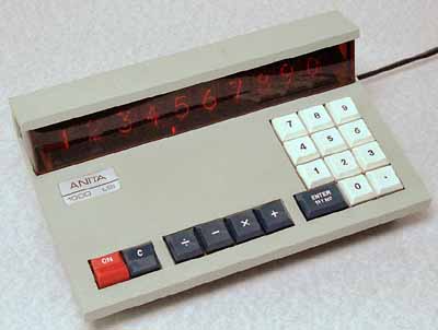
ANITA 1000 LSI calculator.
Following our usual practice of designing and manufacturing everything ourselves as far as possible, the keyboard was a completely new concept. With the considerable reduction in size, we could not continue using the previous keys and switching arrangements. We spent a lot of time perfecting a key-switching arrangement that fitted into the relatively small amount of room available. The contact arrangement comprised a silver-graphite stud and a silver-plated beryllium blade, both soldered into the keyboard printed circuit. The keys comprised two plastic mouldings assembled together with a compression spring between them, the bottom moulding clipping into the printed circuit, and the top moulding, when depressed against its return spring, activating the contacts by pushing the contact blade against the silver-graphite stud. The contact blade was an interesting design exercise. Working closely with Johnston Matthey, a precious metal supplier, and our factory in Portsmouth, we settled on beryllium copper strip about an inch wide with an inlaid silver strip along one edge. In fact, due to their production processes, Johnston Matthey could not supply it in any other form and this created a slight problem. The blade had to have a semi-circular bend at one end and the silver contact area at the other. The bend ensured that the contact acted as a spring and only touched its mating silver graphite stud when pushed downwards by its key. On the face of it, the blades would have to be pierced out of the strip at 90 degrees to the edge of the strip in order that the silver area was at one end of the blade. However, because the strip was produced by a continuous process, the 'grain' of the beryllium copper was along its length which would give the contact blades an inherent weakness across the bend. We had to reach a compromise here by piercing the blades out of the strip at 45 degrees to its length. Our tooling department at Portsmouth did a marvellous job by anticipating the coming of automatic insertion of components into printed circuit boards which is now common practice. They designed a 'progression' tool which progressively pierced the blades from the beryllium copper strip, bent them, formed the legs to match their mating holes in the printed circuit board and then finally inserting the contacts into the various switch positions on the board — all as a continuous sequence of operations.
The ANITA 1000 LSI only weighed about 800 grammes and it became very obvious at the design stage that the size of the integral mains power lead, as required to meet the BSI electrical safety
requirements at that time, was far too heavy for our machine to remain stable on a desk surface. BSI accepted our arguments and allowed us to use a lighter mains power cable. The 1000 LSI series calculators were very
popular with our customers and we were continually introducing enhancements to the range. In fact, it was this machine that prompted some customers to make the point that its size and weight almost made it a portable machine
- except that it had to be connected to a mains electricity supply. The possibility of a battery-operated machine was now very close, but the limited space in the 1000 LSI series for the electronic content precluded the
addition of batteries. Instead we designed an exterior battery 'pod' assembled to the rear of the machine to house a rechargeable battery. It was not the ideal solution. [The resulting machine was the ANITA 1011B LSI, pictured below.]
Copyright © 2001 John Sparkes

The AC/battery-powered ANITA 1011B LSI, the first battery-powered ANITA calculator.

The pod at the rear containing the batteries can easily be seen in this side view of the ANITA 1011B LSI.
Despite all of these developments, one of the largest uses for calculators in the company's home market in Britain was in business and accountancy, for calculations with money. However, until 1971 Britain used the old non-decimal £sd money system which limited the sales there of the early electronic calculators which were decimal. This was eventually catered for by the ANITA Mk10 which could display in £sd, but with decimalisation imminent the cost of this was not easily justified.
So, although the company had a good world-wide dealership organisation, the less vigorous home market for electronic calculators adversely affected the finances of their development.
Reference:
The Bell Punch Company & the Development of the Anita Calculator
< Previous page Next page >
Text & photographs copyright © 2002 - 2023 Nigel Tout, except where noted otherwise.